
Wing and blade tip losses: why vortices form
Wing and blade tip losses come from the fluid flowing around the tip, from the high-pressure face to the low-pressure face: it forms a vortex there that costs lift and adds drag. These losses grow as the wing or blade gets shorter and as the lift concentrates near the tip. The aspect ratio lets us assess them, and Heliciel builds them into the calculation of propellers and wings.
In this article:
- Why the fluid leaks at the wing or blade tip
- Prandtl blade tip loss factor
- Aspect ratio of a wing or blade: formulas and examples
- Reducing tip losses: elliptical wing and winglets
1: Why the fluid leaks at the wing or blade tip
The length of the blade or wing is the third dimension, the one of leaks: blade tip losses.
The formulas for wing drag and lift give theoretical values, which ignore some losses. These theoretical drag and lift, measured in a wind tunnel or calculated by numerical methods, are the 2D (two-dimensional) performance, or "performance of a wing of infinite span". They ignore the third dimension, the length of the blade or wing.
Lift results from the pressure difference between the top and the bottom of the wing. The more the underside pushes and the upper side pulls, the more the wing lifts. But the larger this difference, the more the fluid wants to get to the other side, by the shortest path it finds: the wing or blade tip.
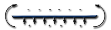
The fluid goes from the overpressure (+) under the wing to the suction (−) above it, flowing around the tip.
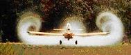
No need for a diagram: wing tip vortices can be seen with the naked eye.
The moral comes in three points:
- the more lift near the wing tip, the more leaks;
- the shorter the blade or wing, the more leaks;
- an ideal blade with no leaks would have an efficiency equal to the 2D performance of its profiles.
2: Prandtl blade tip loss factor
When we calculate the performance of a propeller or a wing in free flow, the fluid is not forced: it can flow around the wing or the propeller. We then use a blade tip loss factor, which accounts for the phenomenon. This factor, expressed by Prandtl, is defined on the page about the tip loss factor and 3D propeller and wing calculation.
It is built into the blade element theory, and the Heliciel software applies it in propeller calculation.
3: Aspect ratio of a wing or blade: formulas and examples
The aspect ratio helps us assess the tip losses of a wing. It is calculated in two ways:
- for a rectangular wing, aspect ratio = span (wing length) / chord (wing width);
- for all wing shapes, aspect ratio = span² / wing area.
The two formulas coincide for a rectangular wing, since the area is then span × chord. Example, with the wings of the figure below: a rectangular wing with a 2 m span and a 0.5 m chord has an area of 1 m², so an aspect ratio of 2² / 1 = 4.
Example of the influence of shape and aspect ratio: the vortex sheets and tip losses of four wings of different shapes and aspect ratios, shown schematically in the Heliciel software.
Rectangular wing, 2 m span: aspect ratio 4, lift-to-drag ratio 16. |
Rectangular wing, 9 m span: aspect ratio 18, lift-to-drag ratio 32. |
| Tapered wing, 2 m span: aspect ratio 5, lift-to-drag ratio 19. | Tapered wing, 9 m span: aspect ratio 33, lift-to-drag ratio 36. |
These four videos show the same effect. A long, slender wing (high aspect ratio) spreads the lift over a large area: the pressure difference between the lower and upper surfaces stays moderate, and the fluid is less tempted to go to the other side. For the same shape, going from 2 to 9 metres raises the lift-to-drag ratio from 16 to 32 for the rectangular wing, and from 19 to 36 for the tapered wing.
4: Reducing tip losses: elliptical wing and winglets
Better still, the lift should be spread as far as possible from the tip: the fluid then has a longer way to go to reach the other side, and the leaks fall. The wing shape that theoretically spreads the lift farthest from the tip is the ellipse. Some aircraft therefore adopted elliptical wings.
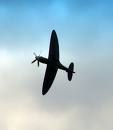
The Spitfire and its elliptical wings, which keep the lift away from the wing tip to limit leaks.
In practice, a trapezoidal shape is enough to get an effect close to the optimum. For the choice of blade shape, the page on the chord distribution of blades and wings describes the method.
Another device reduces tip leakage by placing a barrier: winglets.
Heliciel calculates the performance of propellers and wings including tip losses. The Duct (ignore blade tip losses) box, under the chord graph, excludes them from the calculation: you can then assess the maximum gain that a duct or a winglet system would bring.
In reality, whatever the configuration, tip losses cannot be completely eliminated without generating extra drag, caused by the winglets or other wing tip shapes.
To go further, we can look at how the chord distribution spreads the lift along the blade, or read the page on winglets for blades and wings in Heliciel.
 Global site map
 Mecaflux
 Tutorials Mecaflux Pro3D
 Tutorials Heliciel
 Tutorials Heliciel PRO CFD
 Mecaflux Store
 Compare software functions
 Quotes, Orders, Payment Methods
 project technical studies